Thursday 20 June 2013

Data beberapa diode damper untuk EW


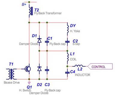
Diode damper untuk sirkit EW ada 2 macam, yaitu
  • D1 - Diode bagian atas yang mempunyai tegangan kerja sekitar 1300~1500v dan
  • D2 - Diode bagian bawah yang mempunyai tegangan kerja sekitar 400~600v yang biasanya juga digunakan untuk penyearah tragangan B+ switching regulator
clip_image002
Berikut ini adalah data beberapa diode damper yang dapat digunakan untuk referensi atau mencari subsitusi (persamaan untuk pengganti).
 
  • BY228        5.0A 1650v
  • BY328        6.0A 1500v
  • BY359        1.0A 1500v
  • BY428        4.0A 1500v
  • BY448        4.0A 1650v
  • BY559        1.0A 1500v
  • BY459        10A 1500v
  • ERC 06-15  1.5A 1500v
  • ERC 06-13  1.5A 1300v
  • ERD 07-15  1.5A 1500V
  • ERD 07-13  1.5A 1300V
  • ER806-15   1.5A  1500v
  • FR309        3.0A 1300v
  • FR3009      3.0A 1300v
  • RH2D         1.0A 1300v
  • RH2F          1.0A 1500v
  • RH3F          2.5A 1500v
  • RH3G         1.5A 1600v
  • RH4F         1.5A 1500V
  • RP3F          2.0A 1300v
  • RS3FS        1.1A 1500v
  • RS4FS        1.5A 1500v
  • RU4D         1.2A 1300v
  • RU4DS        1.5A 1300v


  • BY229-600    8.0A 600v
  • ERD29-06     2.5A 600v
  • FR104          1.0A 400v
  • FR305          3.0A 600v
  • FR3005        3.0A 600v
  • RGP-30J       1.5A 600v
  • RU2M           1.1A 400v
  • RU2AM         1.1A 600v
  • RU3              1.5A 400v
  • RU3A            1.5A 600v
  • RU3M           1.5A 400v
  • RU3AM         1.5V 600v
  • RU3B            1.5A 800v
  • RU3C            1.5A 1000v
  • RU30            3.0A 400v
  • RU30A          3.0A 600v
  • RU4A            1.5A 600v
  • RU4AM          2.0A 600v
  • RU4B            1.5A 800v
  • RU4C            1.5A 1000v
  • RU2M           1.1A 400v
  • RU2AM         1.1A 600v

Tips cara mengganti Def Yoke dengan tipe lain

Dipabrik def-yoke sudah merupakan pasangan tetap yang distel (istilah teknisnya di tune) dengan tepat dengan tabung CRT. Tuning dilakukan dengan menambah dan menempelkan plastik magnetis yang biasa kita lihat saat membuka def yoke.  Def-yoke dan kapasitor resonat sudah dikalkulasi dengan tepat pada sirkit horisontal-out. Merubah nilai impedansi def-yoke atau nilai kapasitor tentu ada efeknya.

menggunakan-crt-monitor-untuk-tv

konfigurasi dari CRT yoke monitor agar dapat di gunakan bersama dengan mesin pesawat TV.Mengapa harus di rubah dahulu? karena nilai resistansi yoke horisontal monitor adalah sangat rendah( mulai 0,2 ohm - 0,6 ohm ) terhadap nilai yang boleh di bebankan kepada sebuah rangkaian defleksi horisontal sebuah

Kode Masuk Setting Factory / Mode Servis TV LG


Cara Masuk Setting Factory atau  Mode Servis untuk TV  LG ada beberapa macam:

  1. Tekan OK di Remote Dan OK Di TV ; atau
  2. Tekan MENU di Remote Dan MENU di TV; atau
  3. Tekan MENU di panel TV2 kali dan tahan lalu tekan MENU di remote. ;  atau
  4. Tekan MENU di remote 2 kali lalu tahan Tekan MENU di panel TV.
  • Untuk Menyimpan Settingan dan keluar dari Mode Servis  tekan Tombol OK.
  • Saran: Untuk menghindari salah Setting, sebaiknya catat dahulu nilai item/bagian yang akan anda rubah. atau paling aman, copy dahulu ini memory-nya dengan alat CopyMemory TV.
semoga bermanfaat.!.

Cara memperbaiki Yoke TV Slim


Pernahkan anda mencoba memperbaiki sendiri Yoke yang putus karena korosi atau terbakar?

Kali ini saya memberikan contoh Cara memperbaiki Yoke TV Slim yang sering saya jumpai, dan sering putus bagian lilitan Verticalnya, dan saya memperbaiki sendiri.


Pernahkah Anda memperbaiki tv model Slim yang gambarnya suman nampak di tengak2 dgn lebar 10 Cm dan gambar bengkok?

Thursday 13 June 2013

Rangkaian Guitar Amplifier + Tone Control

The following is a circuit of amplifiers are equipped with the appropriate regulatory tone in use to strengthen the electric guitar, using a single-rail supply of about 60V and capacitor-coupling for the speaker . The advantages for a guitar amplifier are the very simple circuitry, even for comparatively high power outputs, and a certain built-in degree of loudspeaker protection, due to capacitor C8, preventing the voltage supply to be conveyed into loudspeakers in case of output transistors' failure.
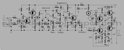
Rangkaian Guitar Amplifier + Tone ControlSkema Rangkaian Guitar Amplifier + Tone Control
In all cases where Darlington transistors are used as the output devices it is essential that the sensing transistor (Q2) should be in as close thermal contact with the output transistors as possible. Therefore a TO126-case transistor type was chosen for easy bolting on the heatsink, very close to the output pair

R30 must be trimmed in order to measure about half the voltage supply across the positive lead of C7 and ground. A better setting can be done using an oscilloscope, in order to obtain a symmetrical clipping of the output wave form at maximum output power

Note:
To set quiescent current, tide ampare meter in series between supplay with this series, then do the following
  • Set the volume control to the minimum and Trimmer R3 to its minimum resistance.
  • Power-on the circuit and adjust R3 to read a current drawing of about 30 to 35mA.
  • Wait about 15 minutes, watch if the current is varying and readjust if necessary.
List component

R1,R2______________68K 1/4W Resistors
R3________________680K 1/4W Resistor
R4________________220K 1/4W Resistor
R5_________________33K 1/4W Resistor
R6,R16______________2K2 1/4W Resistors
R7__________________5K6 1/4W Resistor
R8,R21____________330R 1/4W Resistors
R9_________________47K 1/4W Resistor
R10_______________470R 1/4W Resistor
R11_________________4K7 1/4W Resistor
R12,R20____________10K 1/4W Resistors
R13_______________100R 1/4W Resistor
R14,R15____________47R 1/4W Resistors
R17,R18,R19_______100K 1/4W Resistors
R22__________________6K8 1W Resistor
R23,R25_____________470R 1/4W Resistors
R24__________________2K 1/2W Trimmer Cermet
R26,R27_______________4K7 1/2W Resistors
R28________________220R 1/2W Resistor
R29__________________2K2 1/2W Resistor
R30_________________50K 1/2W Trimmer Cermet
R31________________68K 1/4W Resistor
R32,R33______________R47 4W Wirewound Resistors


C1,C4,C5,C6________10µF 63V Electrolytic Capacitors
C2_________________47µF 63V Electrolytic Capacitor
C3_________________47pF 63V Ceramic Capacitor
C7_________________15nF 63V Polyester Capacitor
C8_________________22nF 63V Polyester Capacitor
C9________________470nF 63V Polyester Capacitor
C10,C11,C12________10µF 63V Electrolytic Capacitors
C13_______________220µF 63V Electrolytic Capacitor
C14,C15,C17,C18________47µF 63V Electrolytic Capacitors
C16________________100µF 25V Electrolytic Capacitor
C19_________________33pF 63V Ceramic Capacitor
C20_______________1000µF 50V Electrolytic Capacitor

P1,P2______________10K   Potentiometers
P3_________________10K   Potentiometer

D1,D2____________BAT46   100V 150mA Schottky-barrier Diodes
D3_________________LED

Q1,Q3____________BC546    NPN Transistors
Q2_______________BC556    PNP Transistor
Q4,Q5____________BD139    80V 1.5A NPN Transistors
Q6_____________MJ11016   120V 30A NPN Darlington Transistor
Q7_____________MJ11015   120V 30A PNP Darlington Transistor

J1,J2___________6.3mm. Mono Jack sockets
SW1,SW2___________SPST Switches
SPKR______________speakers  8 or 4 Ohm with Minimum power 75W
Rangkaian 11-90 hz Subwoofer Filter Using TL072 Op-Amp

The subwoofer filter circuit allows the addition of subwoofers to an existing full-range system, offering adjustable low-pass filtering with optional R6 and R8 boost and mono-summing.
Rangkaian 11-90 hz  Subwoofer Filter Skema Rangkaian 11-90 hz Subwoofer Filter
Using TL072 Op-Amp
TL072 Op-Amp

The Subwoofer filter circuit to remove for separate pre amplifier to drive the low frequency sound a lot. In tone, call tone, normal Can not be done … is a fine deep low bass sounds like a bass drum, or at a movie complex in a low voice if we can be heard with But to add cabinets and amps. The subwoofer circuit is pass low frequency with in 11-90 Hz. Switching power supply 12V cut out if they need to use +-15V. I had change the Capacitor to cut out vocals per the red circle mark.