After more than 30 years of listening, building and enjoying High
Fidelity audio I have become completely convinced that Do-It-Yourself
audio is the best option for people wanting exceptional audio equipment
without taking a second mortgage on their homes. In particular, analog
valve, or tube, audio. Nothing compares to the enjoyment of designing,
building, using and displaying equipment that you built yourself.
Nothing else provides the same opportunity for testing, modifying,
experimenting and learning as homemade audio equipment. And nothing
else will you enjoy using and displaying for many years to come as the
beautiful tube amplifiers that you build yourself.
Probably the greatest single thing about do it yourself audio is that
the designs do not have to appeal to the mass market. Mass produced
equipment has to be marketable and marketing departments have discovered
that features are more marketable to masses than superb musical
quality. Today's marketing strategy says "more watts, lower THD, bigger
woofers, more channels, more bands of equalisation." Basically, bigger
is better, and later is greater. People seeking musical reproduction
will come to discover that none of this has anything to do with
enjoyable music and that systems with fewer watts, more THD, smaller
woofers, fewer channels, and no equalisation often results in a much
more pleasurable listening experience. In short, common specs mean
almost nothing at all.
Watts are undoubtedly today's greatest marketing tool because most
people do not understand what they are and can only assume that more of
them must be better. A 600 watt system must be better than a 50 watt
system, right? Watts are not a measurement of quality but of work. It
is impossible to consider how many watts you need until you know how
efficient your speakers are, how large your listening area is and what
kind of sound pressure level you need to achieve. Measuring an
amplifier in Decibels Referenced to 1 Watt (dBW) is a lot more useful
way to determine what an amplifier is capable of. A 50 watt amplifier
is capable of driving a speaker 17 decibels beyond the 1W/1M rating of
the speaker or, for a 95dB rated speaker, to 112dB. It is not likely
that you would ever need more than this in your living room. If the
speaker could handle it the 600 watt amp could drive it to 123dB but
could only drive an 84dB speaker to 112dB, the same as the 50 watt amp
and the 95dB speaker. So speaker efficiency plays a very important role
in acoustic output. You do not need lots of power if your speakers are
reasonably efficient. Besides this most of the advertised watts today
are fraudulent. How can a $29 amplified computer speaker be 1200 watts
or a $129 shelf system be 600 watts? They can't and aren't.
THD measurements are number two on the list of highly touted but
relatively meaningless, or at least misleading, specifications which can
tell you almost nothing about how an audio component sounds. Correct
ratios of orders of harmonics are a lot more important than low numbers.
This is not a just a theory but can easily be demonstrated.
Furthermore, extremely low THD percentages at rated output tell you that
the amplifier has very high negative feedback levels and is almost a
guarantee of hateful, irritating and unenjoyable sound. Think not?
Try to listen to any amplifier with less than .01% THD on a high
efficiency high resolution speaker and see how long you can stand it.
Also, high Intermodulation Distortion is much more noticable and
annoying than high THD. Why doesn't anyone ever mention this
specification in their marketing scheme?
If specs are your bag I would suggest you look elsewhere because I
simply don't care about them. Enjoyable music is more important to me.
It is far cheaper to acheive impressive specs using cheap solid state
devices than using valves. If sound that makes your heart skip a few
beats is your goal forget about specifications.
Of course the real reason to pursue things that most people consider
obsolete or unreasonable is out of love. My site is intended to provide
resources for others who love analog audio reproduction, phonograph
records, record players, homemade or classic vacuum tube audio
amplifiers and homemade loudspeaker systems.
I am not interested in "Home Theatre" and will not be discussing any related equipment.
Scripting is not necessary to view this site so you may wish to have that turned off while viewing.
All of the
schematics
on this site are listed by category at the bottom of this page but I
hope you will take the time to read my comments about my equipment and
look at the pictures.
Here are some other sites that cater to tube fanatics.
Triode Electronics
of Chicago IL is one of the most informative sites I've ever found on
tube audio, especially with respect to schematics of older equipment.
Another favourite is
Claudio Bonavolt Audio.
La casa di GizMo
is a great and inspiring blog with many beautiful valve projects
including some excellent Compactron amplifier designs. The site is in
Italian but very well worth a look. The craftsmanship and attention to
detail is stunning.
You might also want to look at the following sites...
If you need a tube or tubes for a reasonable price try Doctor Roy at
Radio Tube Supply.
LOTS of New Old Stock and current production tubes at great prices.
Dr. Roy specialises in hard to find types with over 500,000 tubes in
stock. They are some of the nicest people you'll ever deal with, too.
Two other good sources for tube related parts are
Antique Electronic Supply and
The Tube Store.
If you are interested in commercial PA speakers, horns, drivers, and amplifiers you might like to visit my
University Sound Products
site. There is a lot of information to help you identify different
University Sound products. Many of their horns and drivers have been
used successfully in home audio systems as well.
Russell Hamm wrote a paper in 1972 somewhat explaining the difference
in sound between tube and transistor amplifiers as a relationship of
harmonic content and distribution in the harmonic distortion of each
type amplifier. Through Fourier analysis it has been discovered that no
or low feedback tube amplifiers generate mostly low order harmonic
distortion, with a correctly decaying spectrum, which is naturally
present in music anyway, while transistor amplifiers with high feedback
generate high order harmonic distortion devoid of almost all even
harmonics which does not naturally occur in music. Please understand
that there is little an amplifier or any other component can do to make
an improvement in the quality of a signal. Ideally components should
add nothing and take nothing away. Every component adds something to
the signal, however, and it is a matter of which types of distortions
you can live with after every effort has been made to minimise or
eliminate them. Some types of distortion are more harmonically correct
(benign) than other types and appear to our ears to be related to the
music (decaying spectrum) while other types (high and odd) don't appear
to have any relationship at all to the music. This is why Total
Harmonic Distortion figures don't mean anything at all. They don't tell
which orders of distortion are present or in what proportions. If this
interests you, you can read more about it
here.
An important consideration about tubes vs. transistors is their
relationship with the speaker. Transistors generally (not always) have a
lower output resistance than tubes which can result in some "damping"
of the speaker. If the speaker has a relatively high "Q" this can be
useful but if the Q is low the transistor amplifier will sound thin and
lifeless. On the other hand a low Q speaker can benefit from the lower
damping factor of some tube amplifiers but a high Q speaker will boom,
resonate, and sound awful with such low damping. This booming
One-Note-Bass has been attributed to tube amplifiers but is actually a
flaw in the speaker, not the amplifier. Tube amplifiers do not
universally or naturally have to have high output impedances. It is a
result of lower feedback levels generally used in tube amplifiers.
Tubes can be made to have a very low output impedance but these
amplifiers will sound more like transistors than tubes because their
harmonic spectrum is destroyed by high feedback. My experience has been
that damping factors over 50 are of questionable value as the
resistance of cabling, passive crossovers, and the speaker itself exceed
the resistance of the amplifier. Damping factors as low as 2 can sound
surprisingly good under the right circumstances, and a damping factor
of 10 is adequate for many systems. If you are using 16 ohm speakers
you are probably laughing right now as concerns over damping factor and
speaker cable resistance can largely be forgotten about.
If you are really interested in the audible difference between tubes
and transistors go listen to both and make your decision based on what
you hear, not what you read. There is a war going on between fans of
tube and transistor amplifiers and there is hardly any useful unbiased
information to be found regarding the characteristics of each.
How long should the tubes in an amplifier last? Power output tubes
are often rated at 3,000 to 5,000 hours of life when operated
at their limits.
A quality made power tube operated below its design spec limits will
probably last at least twice as long, or 10,000 hours. In your car this
would be like 450,000 to 650,000 miles. At a high average of 5 hours
use per day that comes to 6 1/2 years of service. The tubes in almost
all of my amplifiers are much older than that. Tubes operated well
below their maximum ratings will last even longer and small signal
tubes, since they generally deal with less heat, will last much longer
than that. Heater burnout is not very common. The heaters of later
tube designs are more like the heating elements in your electric range
than the filaments of an incandescent bulb. Failure of passive
components and especially capacitor failure is what usually ruins tubes.
In solid state equipment it's fusing of the junctions or static
discharges that cause the amp to fail. I have found both tubes and
transistors to be very reliable if good quality components are used
throughout. There is a lot of junk being sold today that was not
designed to last but this is mostly imported stuff designed for
"cheapness" rather than "goodness." Unfortunately, this covers almost
all of what is being sold at discount stores and electronics warehouses
these days. Don't think that you'll find any decent HiFi equipment at
any place called "Circuit Town," "Great Buy," or "Ultimate." These are
mass market discount stores, not HiFi dealers as evidenced by the TV
sets, video games, computers, refrigerators, air conditioners, and other
appliances they are selling.
If you are really interested in getting the maximum life out of your
tubes there are some things to observe with this goal in mind. First,
heat kills. Keep them cool. Use a fan or at least holes in the chassis
around the sockets of power tubes to promote lots of airflow. Some say
that cooling the glass envelope cannot help cool the tube because the
anode is cooled by radiation only. The next item in line to deal with
waste heat is the glass envelope and tube ratings are often determined
by how much heat the envelope can handle. Not to mention the effect
that waste heat has on all the other components in the amplifier. Do
not operate tubes above their anode dissipation ratings. This happens a
lot in guitar amplifiers but it will ruin your tubes in a High Fidelity
amplifier. It is best to keep them at or below 80% of rated
dissipation. Second, don't apply power to the plates until the cathodes
are warm. Use a standby switch or other device to keep B+ off the
plates until the tubes are warm. If possible, ramp the voltage up
slowly. Third, don't ever apply more than rated voltage to screen grids
or exceed maximum rated cathode current under any circumstances.
Fourth, do not operate heaters above their rated voltage and reduce
their voltage when the amp is in standby mode and B+ is off. If they
are normally 6.3 volts reduce them to 5.3 when the amp is standing by.
With these simple precautions it may be possible to extend tube life to
near 100,000 hours. Need I say more?
It is necessary to consider a very real problem that when many tube
amplifiers were designed line voltages were 117 and today they are 122
to 125. This 4 or 5 percent increase in line voltage is reflected in
heater and B+ supplies meaning that heaters today may be running at 6.6
to 6.7 volts and B+ has probably picked up 20 or 30 volts as well. It is
best to reduce the voltages, if possible, to their original values. On
class A amplifiers this can be accomplished by placing a resistance of
several ohms in series with the primary winding of the power
transformer. You can calculate the number of ohms needed to drop 5
volts and how much power will be dissipated in the resistor. You may
also consider just increasing the value of the resistor in the screen
supply to lower the screen voltage to acceptable levels. The problem
becomes harder to solve in class AB amplifiers since their current
demands change greatly. You may have to consider a choke input power
supply or you can use a filament transformer whos secondary is wired in
series with, but out of phase with, the primary of your power
transformer.
Here are some more helpful tips for tube amp construction, or
re-construction. Do not ever assume that any component is good or "in
spec." Measure every component, especially if you are using any used
parts. Capacitors and resistors drift way off value and it is possible
that there won't be any useable parts in an old amplifier except for the
tubes and transformers. In a stereo amplifier parts between left and
right channels need to be matched to 1% or better. I hand select every
part by measuring them with a DMM. When first bringing an amplifier up
use a set of tubes (at least the output tubes) that you don't care about
lest something go wrong and you damage or destroy your precious 1950s
NOS RCA black plate valves. I've done this. Have a resistor load and a
scope connected to the outputs the first time you bring it up with
feedback to watch for oscillation. If it does, simply turn it off and
switch the plate leads on the output transformer. And when tuning an
amplifier do a lot of listening and testing with no negative feedback so
you can really tell what is going on in the amp. If it sounds terrible
without feedback the feedback won't fix the problem it will just cover
it up. Design as linear as possible with no feedback and when you add
just a little you will have the magic you are looking for. Power can be
greatly conserved and distortion greatly reduced by limiting the
amplifier's bandwidth to cover only the frequency range that your output
transformer and speaker is capable of reproducing. This is
particularly so with low power single ended designs with small output
transformers. Such limiting must be done before the feedback loop.
Since negative feedback will be inevitable in almost all
applications, consider incorporating a multi-position switch to select
between several measures of feedback so that the amplifier can be more
suitably matched to the loudspeaker and balance can be achieved between
low output resistance and harmonic integrity.
If you are interested in comparing the Rated Output and actual
measured Clipping Output of several different amplifiers I have made a
chart with this information and an explanation of how the equipment was
tested. It doesn't mean very much, really, but it was fun to measure
them. It is available
here.
More of my discussions and opinions about high fidelity equipment,
hinderances to superb reproduction, modifications to equipment, and
setup can be found
here.
This is my second page. It includes some more discussions about
amplifiers plus speakers, turntables, and making the most of what you
already have.
If you are interested in the idea of building small, inexpensive
audio amplifiers out of television tubes which could be used instead of
an IC amplifier in portable and clock radio type applications I have
devised a circuit for this purpose. My page covering the details of
this is
here.
Moving along we'll get into the equipment that I have and to the
circuit diagrams for most of them, plus some other schematics for
equipment that I do not own but have found interesting and thought you
might too.
I have a small collection of
AA5
and AA6 radios. These radios are not particularly valuable to anyone
but me and certainly not because they have a novel circuit design. They
are neat because of the different designs and shapes of the radios
themselves. Most radio collectors seem to like the early wooden radios
best but I am really a fan of the 1950s Bakelite radios. If you are
interested
click here.
Audio Amplifiers and Gear
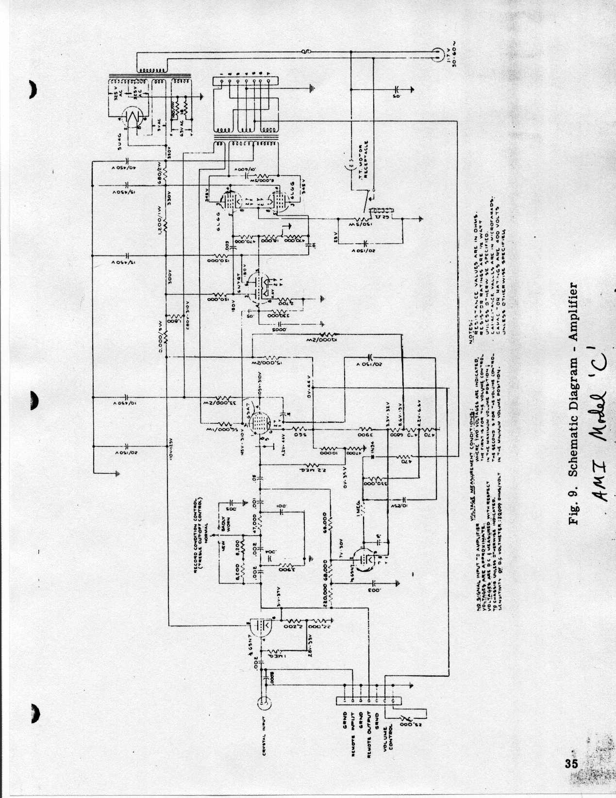
AMI Model C jukebox amplifier. 1949 model that played 78 rpm records. I
tried to fix this amplifier as a teenager but in my attempts to get it
to work better I destroyed the original circuit. I never did get it to
work better but when I was old enough to properly diagnose the problem I
found that it had a shorted output transformer. I found the
circuit diagram
on the Internet so I hope to restore it someday. I do not know what
the rated power output was but it uses two 6L6Gs with cathode biasing
and judging by the circuit configuration and output transformer size I
would suppose it to be about 15dBW. It has a 6SN7, a 6SA7, a 6N7GT, two
6L6Gs, and a 5U4G. Someone had installed two RCA black plate 6L6GCs
before I got it. The model number is "CC" and the serial, 25033. Here
are the
photos.
Someone once gave me a Cones Model 15 pa amplifier but it was in such
bad shape that I couldn't repair it. It looked as if someone had
accidentally run over it. It was very unique, though, because it was
made in Oklahoma City by an unknown company and the serial number was
101. I have wondered if this was the only one in existence and what
ever happened to that company. I couldn't draw the schematic because
the unit was so badly damaged but it was a 12dBw amplifier using two
cathode biased 6V6s and a couple of octal pre-amp tubes. It had a phono
input and a mike input and a simple tone control. The only piece I
saved was the
escutcheon plate
off of the front which gave all the information about the amplifier.
The unit was small, about 7 inches wide, and was built in an open
chassis design.
Flash-A-Call model 2700
intercom unit. This set is in a wooden box but I don't know what year
it is from. A friend wrote and told me he thought it is from around
1947. It is not exactly Hi Fi but it is interesting. It uses a single
50L6 output tube for maybe 3dBW. Similar circuits were common in
portable 78 rpm phonographs of the day. Here is the
schematic. The drawing is poor but readable.
Frazier F-106C power amps. The F-106Cs are fixed bias four 6GT5s per amp.
Press Here.
Beautiful 1962 model MS60a
Grundig Console
set. After cleaning it thoroughly and checking it over it worked very
well. I had to repair a loose connection in the FM I.F. section but
everything else worked without repair. This set has the best AM section
I've ever used. The tuning is very precise and it is very sensitive
and selective. There is a distinct dead space between each frequency on
the band across the entire dial and you can tune it with your eyes
closed as you count the frequencies you are passing. I've listened to
LA from Oklahoma with this radio. Set has a reel to reel recorder and a
shortwave receiver in it, a 3 band speaker system with electrostatic
tweeters, and a cathode biased
push/pull power amplifier
with 6HU8 output tubes. These have an anode rating of 6 watts per
plate. I expect the amp has an output of about 7dBW although I've
never measured it. I do have the schematic for the entire unit. The
power amp circuit would work just as well with 6BQ5s.
Hammond Organ 1969 model E-262, serial number A-33161. 200 means
that it is an institutional model and 62 means that it has a Walnut
finish so the important part is the "E". I acquired the
amplifier chassis,
the speakers (one 15 inch Heppner and two 8 inch), and the remaining
tubes which consisted of some 12AU7s, 12AX7s, and some 6267s. When I
brought the amplifier home and hooked it up it worked beautifully.
None of the tubes needed to be replaced even after 30 years of use. The
main amp is a 16dBW fixed bias amp using 7591As, and the
reverb amp
uses 6GW8s with cathode bias to provide about 11dBw of output. The
main amp has a huge output transformer and it is capable of high
fidelity output with little modification. This amp uses fixed (power
supply) bias. It could easily be converted to use
6L6GCs,
6L6WXT+s, or 6CA7s or even 6550s with modification of the bias and
driver circuitry. Large bulb tubes like KT66s won't fit because the
tubes sit too close together. The reduced load on the power transformer
from the absence of the rest of the organ would make the increased
heater current requirements of these bigger tubes of little consequence.
I have acquired another identical amplifier and naturally have started
converting them into a High Fidelity stereo pair for bi-amplifying.
The amplifiers have a means of balancing the output tubes but they do
not have any way to adjust the idle current for the output stage. One
needs to be incorporated so that the current in each 7591 tube can be
set at 35 to 40mA. There is an error on my drawing. There is a tap on
the secondary of the main amp output transformer which connects to
ground to complete the feedback loop. This is a project that has been
pushed to the back for some time but I hope to be able to take it up
again soon. I believe these amplifiers have a lot of potential.
Harman Kardon A224
stereophonic integrated tube amplifier. 1959 model rated at 11dBW (12
watts) per channel using EL84/6BQ5 output tubes. Also called the "Trio"
this amplifier is the predecessor to a later model called the "Ballad"
or A230. Both use similar circuit topology. The output stage is
cathode biased and is not adjustable. I replaced all of the capacitors
in this amp and have used it for my main amp occasionally for several
years. It is a nice amplifier that works well when used full range or
as a medium to high range amplifier. In full range mode it has plenty
of power for a living room when used with 94dB or higher speakers.
Here is the
schematic.
If you own one and are trying to get the best sound out of it I
suggest replacing all of the ceramic capacitors in the signal path with
film type capacitors. I have replaced the original Amperex France round
getter 6BQ5s (two of which were starting to test marginal after only 45
years of service) with matched 6n14n-EBs and the original small signal
tubes with NOS Sylvanias. Additionally, I changed a bit of the power
supply. I moved the B+ leads of the output transformers to the first
filter capacitor and then replaced the 150 ohm 7 watt resistor (R63)
with one which provides 300 volts on the screens of the 6n14ns, which in
my amp turned out to be 2600 ohms. I also added 40uF to the second
filter capacitor which is right after the 2600 ohm resistor.
Interestingly, the phono preamp in mine does not match the Trio
schematic but rather uses the A230 circuit. And I found that all of the
150k resistors had drifted and were no longer in specification. Most
of the other resistors were still close enough to use.
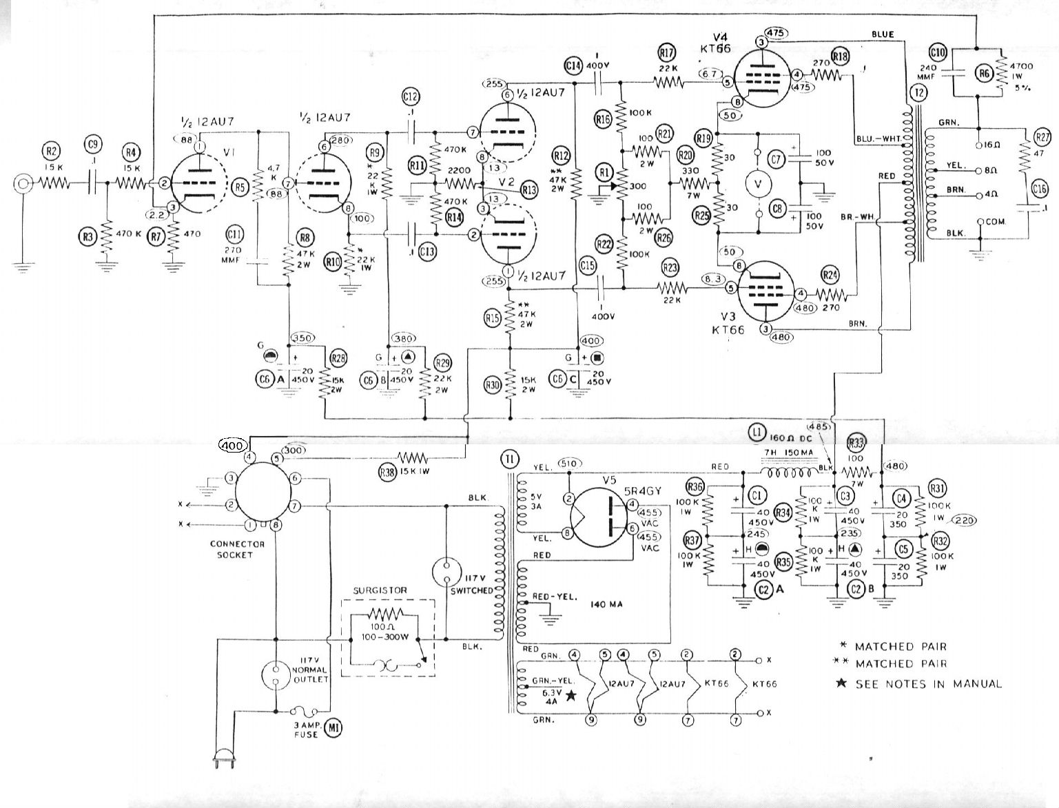
Heathkit W5M Williamson style power amplifier. Two KT66, two 12AU7 and one 5R4GY.
Press Here. Mine are running Sovtek 6L6WXT+ valves and are modified somewhat.
I need to say something about the Sovtek 6L6WXT+ valves and other
current production valves. The 6L6WXT are good quality valves and I am
pleased with them. Ignore the marketing claims "Modeled after the RCA
blackplate" as they are nothing like the RCA and weren't modeled after
anything. They are much heavier 35 watt tubes good for 500+ volts. The
plates never get orange and they are well matched to each other. Some
people have reported as much as 42 watts of dissipation before the
plates start to glow orange. They sound very good and are clean and
balanced throughout the whole audio range. These have been in service in
my Heath W5s for a considerable time with no problems whatsoever.
Sovtek markets a "6L6GC" which is pretty thin for a set of 6L6GCs.
These "GCs" are actually Reflektor 6n3Cs or 6p3Ss and are more like a
6L6GB than a GC. Their plates will start to turn orange above 19 watts
of dissipation and they should not be used above 360 volts. These are
very inexpensive tubes and they will work fine in amplifiers originally
designed for metal 6L6s and 6L6Gs. I have also found that 6n14n and
6n14n-eb valves are very durable and sound at least as good as the other
6BQ5 types I've compared them to. The "EB" type has a plate design
like an Amperex but is even larger and heavier. The plain 6n14n has a
curved plate structure that looks like a small RCA 6L6GB. The sound of
both of these was a big surprise to me. Most reviews of the sound of
different tubes are concerned with guitar applications and the sound of
deliberate distortion at overload with little or no feedback. This does
not apply to high fidelity use so don't believe all you read about
current production tubes. Current producers of tubes are doing a great
service for those of us who love valves. Please do all you can to
support and encourage continued production and developement.
1957 Hoffman model 1107 console phonograph. Unit employs a four
speed Garrard turntable, a bass reflex three band speaker system which
is mounted in a separate enclosure within the console, and an 11 dBW
cathode biased, push/pull
EL84/6BQ5 amplifier.
This amp uses a long tailed pair to invert phase and is direct coupled
to the pentode input stage (Mullard connection.) A very good setup,
indeed. The output transformer is large, perhaps a 20 watt transformer,
which makes saturation at low frequencies impossible. The speaker
enclosure is mounted on springs to prevent feedback from entering the
phono system through the cabinet. It sounded enjoyable when playing old
78 rpm records even though the speaker system is not very well designed
by today's standards. The phono pickup cartridge has failed and I have
yet to replace it.
Early 1950s Masco MA25PN. Has two 6L6Gs, two 6SC7s, four 6J7s, and a
5V4G. Output is rated at 14dBW. Uses an anode follower to invert
phase. The original schematic and all of the photos are
here.
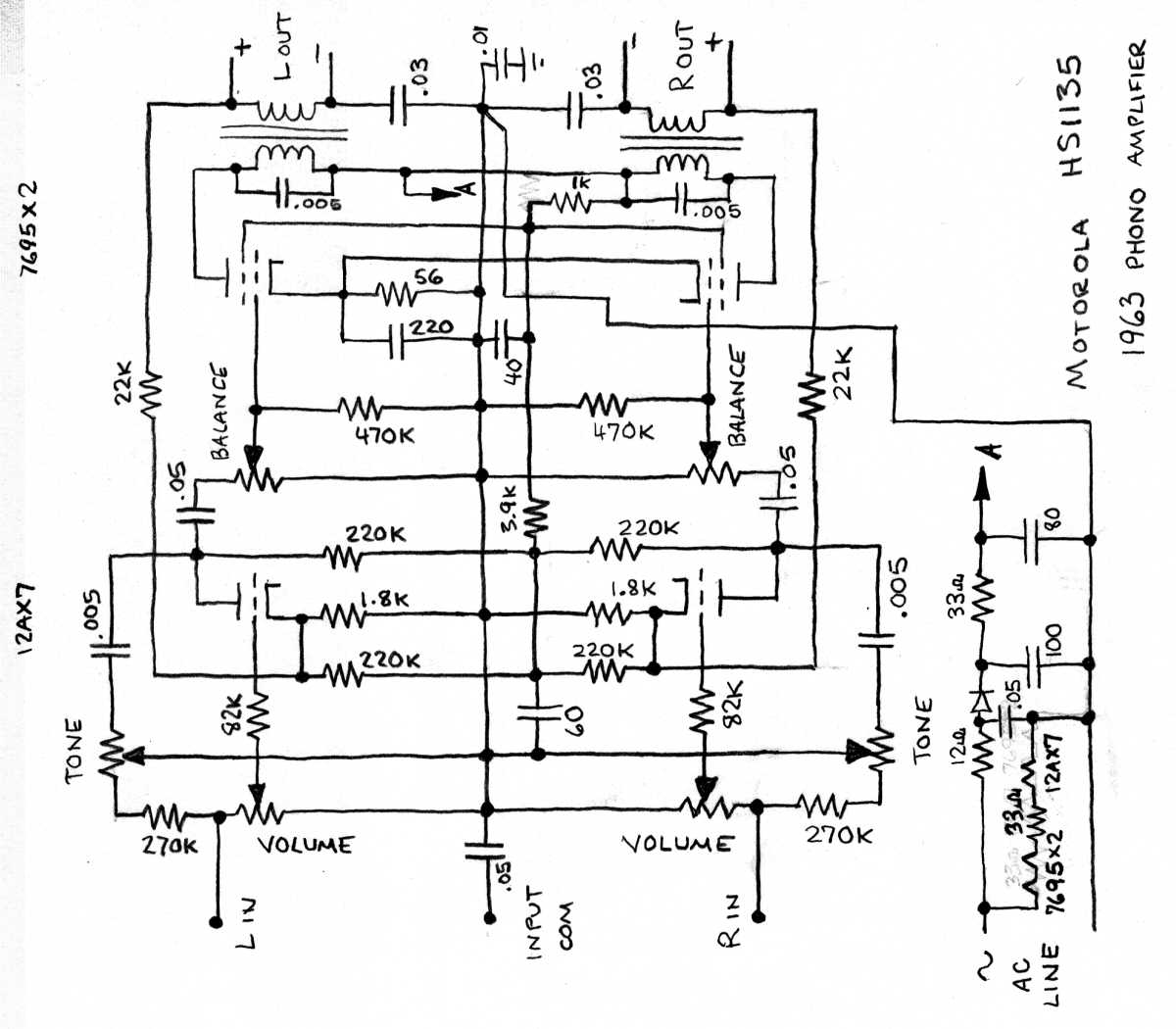
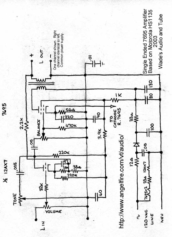
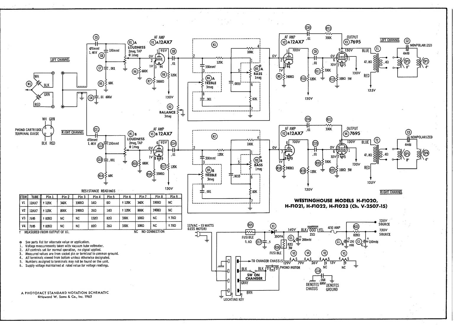
1963
Motorola HS1135
stereo record player amplifier. A two stage, single ended design using
the much overlooked and underestimated beam power tube, the 7695. I
had been aware of this tube for a long time but scoffed at its potential
until working with it in this amplifier. Its ratings are similar to
two parallel 50C5s. RCA and Sylvania manuals say it will deliver 4.5
watts of power (6.5dBW) into 1100 ohms with only 130 volts on the plate.
It requires only 11 volts of input to drive it to full output. This is
similar in output to a single 6AQ5, 6BQ5 or 6V6GT. The amplifier
sounded terrible when I received it. The feedback loop was set up to
emphasise the mid bass, the power supply filtering was insufficient, and
the method of grounding the input, output and chassis was introducing a
lot of noise.
schematic .
Modification was a necessity but I wanted to use as much of the
original circuit as possible. After changing the feedback circuit to
use a small, linear amount, adding capacitance to the power supply,
bypassing the cathode resistors in the 12AX7 stage and eliminating the
noisy grounding system, this amplifier has single ended magic, at least
considering how humble and unsophisticated it is. Vocals and pianos are
right in front of you. Soundstage is 3 dimensional. I did measure its
output at 6.5dBW per channel. It employs 5 watt output transformers.
Here is the
modified schematic.
With 95dB speakers it can play quite loud. It goes without saying that
the feedback resistor can be adjusted to suit your needs. My schematic
suggests a 2200 ohm resistor but I have since tried different values
and have settled on a 1000 ohm resistor. I use this amp without a
preamp so the limiting factor on feedback levels is amplifier
sensitivity since there are only two amplifier stages operating at
relatively low gain. My original intent was to use this amp with an
unbuffered 12AX7 phono preamp, hence the 500k input pot. This value
interacts with the miller capacitance of the input stage and in the real
world 100k would be better. The input grid stoppers can also be
reduced to 1k. Yes, the output impedance is high but such is life with
single ended amplifiers which have only two stages if you want good
input sensitivity. I have also done away with the tone control. I do
not intend to imply that this project is finished, rather that it is
ongoing and this is it's present state.
1965
Precision Electronics 10PA.
A cute little amp which is not too far removed, in size anyway, from
the Cones amplifier mentioned above. It is very tiny for a tube PA
amp. It is rated to present 10dBW of output using a single 6L6GB, a
12AX7, and a 6X5GT. The operating parameters are practically identical
to those of the 8 watt amplifier in the RCA tube manual and in actuality
I measured this amplifier at 9dBW of output. Someone has replaced the
power transformer at some point and this may explain the discrepancy in
power output. It appears that it may be smaller than the original
transformer was. There is also some question as to the value of the
resistor between B+ and the screen supply. 47 ohms seems a little low
to me so this may have been changed. The controls are for one mic, one
aux, and one simple tone control. It will be hard to find any simpler
PA amplifier than this one.
schematic
1945 RCA PA amplifier model MI-12224-A. It has an interesting history.
It started its life as the amplifier for the sound system in the Coyle
theatre in Coyle, Oklahoma. It was taken from that location to the Rex
theatre in Covington, Oklahoma in about 1957. It was used in service
there for several years until it was removed to serve Hi Fi duty in the
dorm room of a young university student attending Oklahoma University in
the early 1960s. The amplifier has two metal 6L6s and was rated 14dBW.
The output transformer is small for a 25 watt amplifier and looks more
like what one might see on a 15 or 20 watt amp. It has a switch which
can be thrown to cut off the low bass response to get more power out of
the smaller transformer. This can be done in PA applications without
affecting the useful performance of the amplifier. When I received it
some of the tubes were missing and it needed the usual capacitor
replacement job. Here is the
schematic. Here are some
photos of what it looked like when I received it. Thank you John Mc for entrusting it to me.
1946 model 612V2 RCA Victrola AM/FM/SW Phono console in a beautiful
Mahogany cabinet. It has a 12 inch field coil loudspeaker and separate
bass and treble controls. I drew the
power amp diagram
when I was replacing capacitors but now have the Riders Schematic for
the whole unit. The amplifier uses a conventional split load phase
inverter but does not have enough gain to be used as a power amp with
anything modern unless you add another stage of gain to it. It uses
quasi-fixed bias from voltage developed across a 180 ohm resistor and
has no global feedback at all. I measured it's output at 11dBW which I
thought reasonable for a push-pull pair of 6F6s. Original
specifications list the unit as a 10 watt amplifier and I suspect todays
higher line voltage accounts for the difference in power. 6V6s can be
installed without modification.
Single Ended
6AQ5 Stereo Amplifier.
My own design based partly on a Zenith design which makes good use of
the inexpensive 6AQ5 valves. This amp uses a single 12AX7 and one 6AQ5
per channel and is able to drive each speaker at least 6dB beyond 1W. I
retained the tube rectifier (5Y3GT) and 5 watt Zenith 95-1652 output
transformers. I am using a black plate Zenith 5Y3GT and an Amperex
Bugle-Boy ECC83/12AX7 and am switching between black plate Zenith and
RCA and grey plate GE 6AQ5As. Zenith chose a 1k2 cathode resistor for
the first stage but 2k7 may be a better choice although I've not tried
it to see.
schematic.
In my amp B+ is 290 volts but the screens are at 249 and I've had no
problem with the high voltage on the plates. The output impedance is a
little high with a 1k feedback resistor and open loop
loaded output is reduced about 7dB. A 400 ohm resistor will reduce
loaded
output about 11dB but will cut output impedance by more than half.
Presently I am auditioning 330 ohm feedback resistors and the sound in
full range mode suggests much lower output impedance. If using with a
preamp the amp has enough gain to use, within reason, about as much
feedback as you want to. My original intent was to use this amp with an
unbuffered 12AX7 phono preamp, hence the 500k input pot. This value
interacts with the miller capacitance of the input stage and in the real
world 100k would be better. The input grid stoppers can also be
reduced to 1k. I do not intend to imply that this project is finished,
rather that it is ongoing and this is it's present state.
Single Ended
6BQ5/EL84 Stereo Amplifier. Another part Zenith/part my-own design.
Single Ended 6V6GT Stereo Amplifier. My own design, similar to 6AQ5
amp above, but using 6V6GTs and 10 watt RCA 972623-12 output
transformers. The amplifier is also two stages and uses 5Y3
rectification. This amp was to make use of the additional voltage
handling and plate dissipation abilities of the larger 6V6. Input stage
is the venerable 12AX7. All valves in this amplifier are RCA black
plates with date code 58-22. Output is about 1dB more than the 6AQ5
amp. An alternate topology might be to use two stages of 6CG7 or 6SN7
or an SRPP setup rather than a single stage of 12AX7 to drive the output
tubes. This amp sounds remarkably similar to the 6AQ5 amp above with
good low frequencies, full midrange and slightly dark highs. For 4 ohm
use one could use 6L6 rather than 6V6 tubes since they require roughly
half the load impedance. This would also increase the output power a
bit.
schematic.
My original intent was to use this amp with an unbuffered 12AX7 phono
preamp, hence the 500k input pot. This value interacts with the miller
capacitance of the input stage and in the real world 100k would be
better. The input grid stoppers can also be reduced to 1k. Pictures to
come shortly. I do not intend to imply that this project is finished,
rather that it is ongoing and this is it's present state.
Spox Stereo Speaker Originally designed to upgrade an existing monaural installation to stereo. It has a built in single ended
6BQ5 amplifier
which I measured at 6dBW of output. It will play louder than you might
expect from looking at it. It has two, evidently efficient, 6 inch
speakers. If you build a stereo amplifier from this circuit and do not
plan to include tone controls you can dispense with the first 12AX7
stage in each channel, meaning only one 12AX7 is required to cover both
left and right channels.
Late 1940s Webster Electric Company 95B25. Has two 6L6s, a 6SL7, a
6SJ7, a 6SC7, an 0A3, and two 6X5GTs with two mic inputs and one
auxillary input. Rated 14dBW. This amplifier uses "fixed bias" but one
very important thing I did was to replace the selenium bias rectifier
with a silicon rectifier. You should do that on any amp you have that
uses selenium rectifiers. The amp uses a separate triode stage commonly
called "paraphase" or "anode follower" to invert phase for one of the
output tubes. If you have any Webster amplifier schematics that you
would like to have listed on this site please
e-mail me. Remove the two Xs from the address. Here is my
Webster Electric page. I now have two other Webster Electric amplifiers and the schematics and photos of these are on
that page.
1959 Zenith
Cobramatic Phonograph.
It is a stereophonic system using single ended 6AQ5s. The 6AQ5 is a
miniature (7 pin) 6V6. The original circuit was not suitable for high
fidelity use today as it had permanent frequency manipulation built in
to the feedback circuit and volume control. With modification this
could be made into a very nice amplifier with one 12AX7, two 6AQ5s and
one 5Y3GT. See my 6AQ5 amplifier above. When I received the set all of
the capacitors and several of the resistors had already failed.
1959 model Zenith SRS12W stereo upgrade amplifier from a stereo
upgrade speaker unit with a 12" woofer and a 5" high frequency speaker.
Uses an anode follower phase inverter.
Press Here .
1939 model
Zenith table radio and phonograph
in a beautiful large wooden cabinet. Electronics work but the crystal
phono cartridge needs to be replaced. I don't have a circuit diagram
for this one. Single ended 6V6 output and uses a field coil
loudspeaker.
Here are some schematics from books that I have. I do not own any of
these and have never tried any of them. They will likely work fine
however since they come from dependable sources.
10 watt (10dBW) amplifier from 1950s "Electronic Communication" textbook, 2 6BQ5
schematic.
8 watt (9dBW) amplifier from RCA Receiving Tube Manual, 1 6L6
schematic.
The following amplifiers have tubes that are not so common today but
they can be replaced with tubes that are more easily obtained.
15 watt (12dBW) amplifier from RCA Receiving Tube Manual, 2 7189
schematic. Will work fine with 6BQ5s.
30 watt (15dBW) amplifier from RCA Receiving Tube Manual, 2 7868
schematic. Can also use 6L6 family tubes.
50 watt (17dBW) amplifier from RCA Receiving Tube Manual, 2 7027A
schematic parts list. Will work great with 6L6GCs.
My second page is called
Other Topics Concerning High Fidelity.
My comparison of
Rated Power vs. Measured Power in audio amplifiers.
How to build
Audio Amplifiers From TV Compactrons.
Discussion and information about the
Minimus 7 family of speakers.
If you like high efficiency horns, drivers, and amplifiers you might like to visit my
University Sound Products site. Some of their speaker components are suitable for use in High Fidelity installations.
Here is a complete list of all the schematics on this site. Some of
the file sizes are rather large but I used the smallest file size I felt
would give you acceptable image quality when you print the image on
your printer. They will not fit on the screen of your computer and you
should not print them directly from this webpage but save them and print
them through an imaging or other graphics program.

Tube Stuff
Single Ended
- All American 5 Tube radio, 1 50C5 schematic (60k)
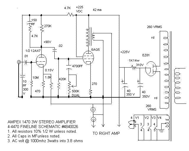
- Ampex 1470 Tape Deck power amplifier, 1 6AQ5 schematic (51k) Provided courtesy of Steve Gates and John Warmack.
- Bogen SA10-40 Intercom, 1 6L6 schematic (100k)
- Compactron TV tube single ended amplifier, 1 17BF11 (approx 3dBW) schematic (75k)
- Flash-A-Call 2700 Intercom, 1 50L6 schematic (93k)
- Lafayette SK-256 Reverb System 3dBW amplifier, 1 30A5 schematic (179k)
- Harmony H400 3dBW guitar amplifier, 1 50C5 schematic (87k)
- Modified Motorola 7695 single ended amplifier, 1 7695 schematic (104k)
- Motorola HS1135 6dBW single ended amplifier, 1 7695 schematic (93k)
- Precision Electronics 10-PA 10dBW PA amplifier, 1 6L6GB schematic (119k)
- RCA 9dBW amplifier, 1 6L6 schematic (73k)
- Single Ended Two Stage 6dBW Stereo Amplifier, my own design (Zenith Chassis), 1 6AQ5 schematic (93k)
- Single Ended Two Stage 7dBW Stereo Amplifier, my own design (Zenith Chassis), 1 6BQ5 schematic (95k)
- Single Ended Two Stage 7dBW Stereo Amplifier, my own design (RCA Chassis), 1 6V6GT schematic (93k)
- Spox amplified speaker, 1 6BQ5 (approx 6dBW) schematic (37k)
- Westinghouse H-F1020 to H-F1023 6dBW amplifier, 1 7695 schematic (242k)
Push-Pull Cathode Biased
- 10dBW amplifier, 2 6BQ5 schematic (48k)
- AMI Model C Jukebox amplifier, 2 6L6G (approx 14dBW) schematic (212k)
- Grundig Majestic MS60a power amp, 1 6HU8 (approx 8dBW) schematic (155k)
- Hammond Organ Type E 11dBW reverb amplifier, 2 6GW8 schematic (110k)
- Hammond Organ Type F 2A3 amplifier - See Webster 6122A-1A below
- Harman Kardon A224 11dBW/channel Stereo amplifier, 2 6BQ5 schematic (191k)
- Harman Kardon A230 12dBW/channel Stereo amplifier, 2 6BQ5 schematic (138k)
- Heathkit W5M 14dBW power amplifier, 2 KT66 schematic (253k)
- Hoffman 1107 11dBW power amplifier, 2 6BQ5 schematic (71k)
- Knight SX14L721 AM/FM Receiver-Amplifier, 2 6V6GT schematic page 1 (110k), schematic page 2 (114k)
- Masco MA-25PN 14dBW PA amplifier, 2 6L6G schematic (103k)
- Masco MA-35 15dBW PA amplifier, 2 6L6GA schematic (210k)
- RCA 12dBW amplifier, 2 7189 schematic (85k)
- RCA 15dBW amplifier, 2 7868 schematic (88k)
- RCA MI-12224-A 14dBW PA amplifier circa 1945, 2 6L6 schematic (134k)
- RCA Victrola 612V2 11dBW power amplifier, 2 6F6G schematic (89k)
- Webcor 1968/1969 9dBW amplifier, 2 12AB5 schematic (164k)
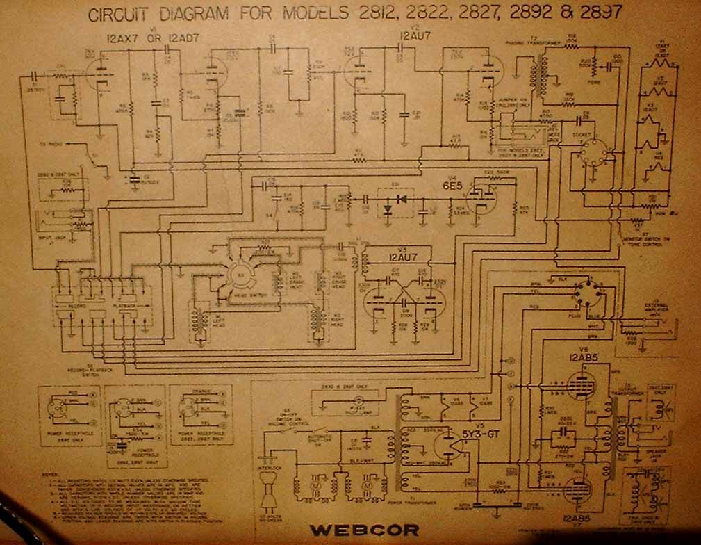
- Webcor 2812, 2822, 2827, 2892 and 2897 Reel Recorders, 2 12AB5 schematic (125k) Many thanks to Craig R. for providing this schematic
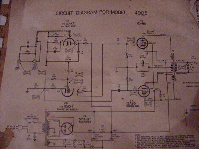
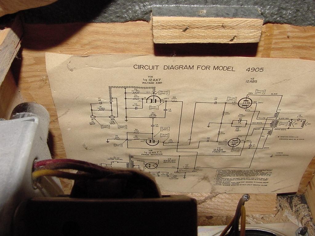
- Webcor 4905 9dBW amplifier, 2 12AB5 First scan (poor) schematic (38k) , Second scan (better) schematic (169k)
- Webster 6122A-1A Parallel Push Pull 2A3 amplifier schematic (77k)
- Webster 81B15 12dBW PA amplifier, 2 6V6 schematic (96k)
- Webster TP14 11dBW PA amplifier, 2 6V6GT schematic (141k) Gracious thanks to Art K. for providing this schematic
- Zenith SRS12W 11dBW amplifier, 2 6BQ5 schematic (128k)
- Zenith (Modified) 11dBW amplifier, 2 6BQ5 schematic (103k)
Push-Pull Fixed Bias
- Genelex 26dBW amplifier, 10 KT88 schematic (42k)
- Grommes-Precision-Frazier G-101A, F-106C 20 dBW power amplifier, 4 6GT5 schematic (39k)
- Hammond Organ Type E 16dBW main amplifier, 2 7591A schematic (104k)
- Heathkit AA-50 14 dBW Integrated Amplifier, 2 7591A schematic page 1 (344k), schematic page 2 (334k)
- Leslie 102 4 channel amplifier, 2 7189 schematic (98k) A really poor scan but hopefully it will be of some use to you.
- RCA 17dBW amplifier, 2 7027A schematic (72k) parts list (46k)
- Webster 95B25 14dBW PA amplifier, 2 6L6 schematic (102k)
- Webster TP45 17dBW PA amplifier, 2 6L6GC schematic (169k)
- Webster WSA230 24dBW (230 watt) amplifier, 4 8417 schematic (168k)
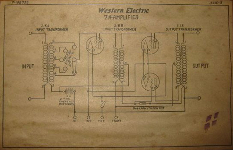
- Western Electric 7A 3 tube amplifier, 3 216a schematic (93k)
Pre-Amplifiers and Miscellany
Solid State Stuff
I add to this site as I have time and as I get new schematics and new ideas. Please visit again to see what's changed.


![[Gambar: new-skema-ampli-trafo-3055-revisi1.jpg]](https://lh3.googleusercontent.com/blogger_img_proxy/AEn0k_sDb2Sloq-2CZL-T7bMxjCC35c2NtgSYBGFBMjhPEJIjlgOeu6Dj7pq8Z144E07__JQoCR9uIEwaPedT6_JjzvtX24l5kvFL3CC3rgusrEQC5WVFBIYy7nwoEIb7Vf9ux2266KUmv_ACIPQaV7Cd2kue6A9aK49N4hD338l=s0-d)


 I wanted to do a simple project that would be easy and cheap for a beginner to build.
A good single transistor design can do the job well. Let's just extract a section of the
classic Big Muff, modify it slightly and use it as a single booster stage. It can provide over 30db of gain
and will be fairly low noise.
I wanted to do a simple project that would be easy and cheap for a beginner to build.
A good single transistor design can do the job well. Let's just extract a section of the
classic Big Muff, modify it slightly and use it as a single booster stage. It can provide over 30db of gain
and will be fairly low noise.


 Referensi